Appendix D. Weirs and Flume Size and Flow Calculations
D.1 Weirs
Selection of a weir should take into account the range of flow measurement. Recommended ranges are:
- high flows (132,000 gpm - 30,000 m3/h: rectangular weir with or without final contractions.
- medium flows (50,000 gpm - 12,000 m3/h): rectangular weir with or without final contractions.
- low flows (13,000 gpm / 3,000 m3/h): triangular weir
Flow can be calculated using the following continuity equation:
Q = v A = Cd A (2 g H) ½
where:
Q = Flow in units of volume/time; for example in m3/s,
V = Fluid speed in units of length/time; for example in m/s,
A = Area where the fluid pass through with “V” velocity in units of surface; for example in m2,
g = Gravitational acceleration constant: 9.81 m/s2,
H = Water level in the weir, measured vertically from the headA specific measurement of water pressure above a geodetic datum. It is usually measured as a water surface elevation expressed in units of length. above the weir crest to the point of the effective head.
Cd= Discharge coefficient, determined experimentally
The following equations could be used in steady-state flow conditions with a free surface (discharge exposed to air) and employing dimensions recommended flows.
In order to obtain original equations, which can be used in a wide range of situations, please consult (Grant and Dawson 1997).
D.1.1 Broad-crested weir
Q [L/s] = 1,838 L H1.5
where:
Q = Flow (L/s)
H = Head of water approaching the weir (m)
L = Weir Length (m)
LH= Measurement point of H (m)
Z = Proximity zone

Figure D-1. Rectangular weir without final contractions [Hmax = maximum dimension = 2 * H = 2hmax].
Source: CPTS (2009).
|
Length, L [m] |
Minimum height H [m] |
Maximum height H [m] |
Minimum flow [L/s] |
Maximum flow [L/s] |
|---|---|---|---|---|
|
0.3 |
0.06 |
0.15 |
8.11 |
32.0 |
|
0.4 |
0.06 |
0.20 |
10.8 |
65.8 |
|
0.5 |
0.06 |
0.25 |
13.5 |
115 |
|
0.6 |
0.06 |
0.30 |
16.2 |
181 |
|
0.8 |
0.06 |
0.40 |
21.6 |
372 |
|
1.0 |
0.06 |
0.50 |
27.0 |
650 |
|
1.5 |
0.06 |
0.75 |
40.5 |
1,790 |
|
2.0 |
0.06 |
1.00 |
54.0 |
3,680 |
|
3.0 |
0.06 |
1.50 |
81.1 |
10,100 |
D.1.2 Rectangular weir
Q [L/s] = 1,838 (L – 0.2 H) H1.5
where:
Q = Flow (L/s)
H = Head of water approaching the weir (m)
L = Weir Length (m)
LH = Measurement point of H (m)
Z = Proximity zone

Figure D-2 Rectangular weir with final contractions [Hmax = maximum dimension = 2 * H = 2hmax].
Source: CPTS 2009
|
Length, L [m] |
Minimum height H [m] |
Maximum height H [m] |
Minimum flow [L/s] |
Maximum flow [L/s] |
|---|---|---|---|---|
|
0.3 |
0.06 |
0.15 |
7.8 |
28.8 |
|
0.4 |
0.06 |
0.20 |
10.5 |
59.2 |
|
0.5 |
0.06 |
0.25 |
13.2 |
103 |
|
0.6 |
0.06 |
0.30 |
15.9 |
163 |
|
0.8 |
0.06 |
0.40 |
21.3 |
335 |
|
1.0 |
0.06 |
0.50 |
26.7 |
585 |
|
1.5 |
0.06 |
0.75 |
40.2 |
1,610 |
|
2.0 |
0.06 |
1.00 |
53.7 |
3,310 |
|
3.0 |
0.06 |
1.50 |
80.7 |
9,120 |
D.1.3 Triangular weir (also called v-notch) (ISO 4371)
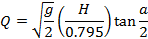
where:
Q = Flow (L/s)
g = Acceleration due to gravity = 9.8066 m/s2
H = measured water depth and end of channel
a = Apex Angle: angle at the bottom of Triangle
|
Angle (a) |
Flow formula(1) [L/s] |
Minimum height H [m] |
Maximum height H [m] |
Minimum flow [L/s] |
Maximum flow [L/s] |
|---|---|---|---|---|---|
|
30° |
Q = 373.2 H2.5 |
0.06 |
0.6 |
0.329 |
104 |
|
45° |
Q = 571.4 H2.5 |
0.06 |
0.6 |
0.504 |
159 |
|
60° |
Q = 796.7 H2.5 |
0.06 |
0.6 |
0.703 |
222 |
|
90° |
Q = 1,380 H2.5 |
0.06 |
0.6 |
1.220 |
385 |
|
120° |
Q = 2,391 H2.5 |
0.06 |
0.6 |
2.110 |
667 |
(1) H, level in meters

Figure D-3. Triangular weir [Hmax = maximum dimension = 2 * H = 2hmax].
Source: CPTS 2009.
D.2 Parshall Flumes
The hydraulic equation to determine the flow using a Parshall flume is:
Q = x W (y H)n
where:
Q = Flow, L/s
W = Throat width, m
H = Depth of a defined section before the obstruction, m
x, y, n = Calibration coefficients of the Parshall flume used
Table D-4 was elaborated using Parshall flume scheme shown in Figure D-4. According to AF-IPK/CNI (1999) the formula for the determination of the flow is:
Q [m3/s] = 0.1132 W (3.28 H)n
where:
Q = Flow, L/s
W = Throat width, m
H = Depth of a defined section before the obstruction, m
n = Constant
For W > 1 ft => n = 1.522 x W 0.026

Figure 1. Parshall flume schematic.
Source: Fuente, AF-IPK/CNI (1999).
|
W |
W |
W |
A |
2/3 A |
B |
C |
D |
E |
F |
G |
K |
M |
N |
n |
MIN |
MAX |
|---|---|---|---|---|---|---|---|---|---|---|---|---|---|---|---|---|
|
in |
ft |
mm |
mm |
mm |
Mm |
mm |
mm |
mm |
mm |
mm |
mm |
mm |
mm |
constant |
m3/h |
m3/h |
|
1 |
1/12 |
25.4 |
363 |
242 |
356 |
93 |
167 |
229 |
76 |
203 |
19 |
|
29 |
1.550 |
0.5 |
16 |
|
2 |
1/6 |
50.8 |
414 |
276 |
406 |
135 |
214 |
254 |
114 |
254 |
22 |
|
43 |
1.550 |
1.1 |
31 |
|
3 |
1/4 |
76.2 |
467 |
311 |
457 |
178 |
259 |
457 |
152 |
305 |
25 |
305 |
57 |
1.547 |
2.8 |
189 |
|
6 |
1/2 |
152.4 |
621 |
414 |
610 |
394 |
397 |
610 |
305 |
610 |
76 |
305 |
114 |
1.580 |
5.5 |
400 |
|
9 |
3/4 |
228.6 |
879 |
587 |
864 |
381 |
575 |
762 |
305 |
457 |
76 |
305 |
114 |
1.530 |
9.3 |
900 |
|
12 |
1 |
304.8 |
1,372 |
914 |
1,343 |
610 |
845 |
914 |
610 |
914 |
76 |
381 |
229 |
1.522 |
12 |
1,645 |
|
|
1 1/2 |
457.2 |
1,448 |
965 |
1,419 |
762 |
1,026 |
914 |
610 |
914 |
76 |
381 |
229 |
1.539 |
17 |
2,500 |
|
|
2 |
609.6 |
1,524 |
1,016 |
1,495 |
914 |
1,207 |
914 |
610 |
914 |
76 |
381 |
229 |
1.549 |
44 |
3,370 |
|
|
3 |
914.4 |
1,676 |
1,118 |
1,645 |
1,219 |
1,572 |
914 |
610 |
914 |
76 |
381 |
229 |
1.566 |
63 |
5,140 |
|
|
4 |
1,219.0 |
1,829 |
1,219 |
1,794 |
1,524 |
1,937 |
914 |
610 |
914 |
76 |
457 |
229 |
1.578 |
130 |
6,920 |
|
|
5 |
1,524.0 |
1,981 |
1,321 |
1,943 |
1,829 |
2,302 |
914 |
610 |
914 |
76 |
457 |
229 |
1.587 |
158 |
8,730 |
Publication Date: November 2013